Circuit
Claude haiku 5.5 · full
Reviews & generation details
Reviews
No human review yet. Unreviewed does not mean unsuccessful.
Generation context
Task text captured before this run. Effective runtime system instructions were not captured.
Generation prompt · 294022e0a1
Act as an expert electronics engineer and technical writer. Create a complete, beautifully styled HTML guide for building a stereo audio amplifier circuit from scratch on a breadboard.

Style it with embedded CSS (clean, modern, dark-mode or tech-themed design, responsive layout) and use inline SVG graphics for any circuit diagrams. Do not use external CSS or image links.

The guide must include the following sections:

1. **Header & Introduction**: Title, brief overview of how a basic audio amplifier works (using an LM386 dual setup or similar classic stereo op-amp configuration), and what the user will achieve.
2. **Safety & Prerequisites**: Essential workbench safety, tools needed (soldering iron is optional since it's breadboard, wire cutters, multimeter, audio source, speakers), and basic components knowledge.
3. **Complete Parts List**: A detailed bill of materials in a clean HTML table, including:
   - Component Name / Part Number (e.g., LM386 Low Voltage Audio Power Amplifier IC, 10µF capacitors, 220µF capacitors, 10k potentiometer, 8-ohm speakers, 9V battery or power supply, jumper wires, breadboard).
   - Quantity.
   - Purpose/Role in the circuit.
4. **Circuit Diagrams**:
   - Provide clear, well-labeled schematic diagrams rendered using inline SVG.
   - Include both a schematic symbol view and a visual breadboard wiring guide view to help beginners map pin-to-pin connections.
5. **Step-by-Step Assembly Instructions**: Numbered, detailed steps guiding the user from placing the IC on the breadboard, adding power rails, decoupling capacitors, volume control potentiometer, audio input jack, to finally connecting the stereo speakers.
6. **Testing & Troubleshooting**: Common mistakes to watch out for (e.g., reversed polarity, loose grounds, feedback loops) and how to test the circuit safely before powering it up.

Ensure the HTML is clean, semantic, and visually polished with clear typography, code blocks or tables for parts, and well-designed SVG graphics.
Inspect original source 42,952 bytes · SHA-256 bc6f0f885d31
<!DOCTYPE html>
<html lang="en">
<head>
<meta charset="UTF-8">
<meta name="viewport" content="width=device-width, initial-scale=1.0">
<title>Build a Stereo Audio Amplifier on a Breadboard | LM386 Field Guide</title>
<style>
:root {
--bg: #0b0f14;
--panel: #121a23;
--panel-2: #172330;
--line: #22313f;
--text: #d7e2ec;
--muted: #8397a8;
--accent: #3ddc97;
--accent-2: #4cc3ff;
--warn: #ffb347;
--danger: #ff5c6c;
--mono: "SFMono-Regular", Consolas, "Liberation Mono", Menlo, monospace;
--sans: system-ui, -apple-system, "Segoe UI", Roboto, Helvetica, Arial, sans-serif;
}
* { box-sizing: border-box; }
html { scroll-behavior: smooth; }
body {
margin: 0;
background: radial-gradient(1200px 600px at 10% -10%, #15273a 0%, var(--bg) 60%) fixed, var(--bg);
color: var(--text);
font-family: var(--sans);
line-height: 1.65;
font-size: 16px;
}
a { color: var(--accent-2); text-decoration: none; }
a:hover { text-decoration: underline; }
.wrap { max-width: 1100px; margin: 0 auto; padding: 0 22px; }
header.hero {
padding: 72px 0 56px;
border-bottom: 1px solid var(--line);
background: linear-gradient(180deg, rgba(61,220,151,0.06), transparent);
}
.eyebrow {
font-family: var(--mono); color: var(--accent);
font-size: 13px; letter-spacing: 0.18em; text-transform: uppercase;
}
h1 { font-size: clamp(2.1rem, 5vw, 3.4rem); line-height: 1.1; margin: 12px 0 16px; letter-spacing: -0.02em; }
h1 span { color: var(--accent); }
.lead { color: var(--muted); font-size: 1.12rem; max-width: 760px; }
.meta-chips { display: flex; flex-wrap: wrap; gap: 10px; margin-top: 26px; }
.chip {
font-family: var(--mono); font-size: 13px; padding: 6px 12px;
border: 1px solid var(--line); border-radius: 999px;
background: var(--panel); color: var(--muted);
}
.chip b { color: var(--accent-2); font-weight: 600; }
nav.toc {
position: sticky; top: 0; z-index: 10;
background: rgba(11,15,20,0.9); backdrop-filter: blur(8px);
border-bottom: 1px solid var(--line);
}
nav.toc ul {
list-style: none; margin: 0; padding: 10px 0;
display: flex; gap: 6px; flex-wrap: wrap; justify-content: center;
}
nav.toc a { color: var(--muted); font-size: 14px; padding: 6px 12px; border-radius: 8px; display: inline-block; }
nav.toc a:hover { background: var(--panel-2); color: var(--text); text-decoration: none; }
main section { padding: 56px 0 8px; scroll-margin-top: 70px; }
section h2 { font-size: 1.8rem; margin: 0 0 6px; letter-spacing: -0.01em; }
section h2 .num { font-family: var(--mono); color: var(--accent); font-size: 0.8em; margin-right: 10px; }
section h3 { font-size: 1.15rem; margin: 30px 0 10px; color: #eef5fb; }
.sub { color: var(--muted); margin: 0 0 24px; }
p { margin: 0 0 14px; }
ul.clean { padding-left: 20px; margin: 0 0 16px; }
ul.clean li { margin-bottom: 6px; }
.card {
background: linear-gradient(180deg, var(--panel-2), var(--panel));
border: 1px solid var(--line); border-radius: 14px;
padding: 22px 24px; margin-bottom: 20px;
}
.card h3:first-child { margin-top: 0; }
.grid-2 { display: grid; grid-template-columns: repeat(auto-fit, minmax(260px, 1fr)); gap: 18px; }
.callout {
border-left: 4px solid var(--accent-2); background: rgba(76,195,255,0.06);
padding: 14px 18px; border-radius: 0 10px 10px 0; margin: 18px 0;
}
.callout.warn { border-color: var(--warn); background: rgba(255,179,71,0.07); }
.callout.danger { border-color: var(--danger); background: rgba(255,92,108,0.08); }
.callout strong { display: block; margin-bottom: 4px; font-family: var(--mono); font-size: 13px; letter-spacing: 0.06em; text-transform: uppercase; color: var(--accent-2); }
.callout.warn strong { color: var(--warn); }
.callout.danger strong { color: var(--danger); }
.table-wrap { overflow-x: auto; border: 1px solid var(--line); border-radius: 14px; margin: 14px 0 24px; }
table { width: 100%; border-collapse: collapse; font-size: 15px; }
thead th {
text-align: left; background: var(--panel-2); color: var(--accent);
font-family: var(--mono); font-size: 12px; text-transform: uppercase; letter-spacing: 0.08em;
padding: 12px 14px; border-bottom: 1px solid var(--line); white-space: nowrap;
}
tbody td { padding: 12px 14px; border-bottom: 1px solid var(--line); vertical-align: top; }
tbody tr:last-child td { border-bottom: none; }
tbody tr:nth-child(even) { background: rgba(255,255,255,0.015); }
td.qty { font-family: var(--mono); color: var(--accent-2); text-align: center; white-space: nowrap; }
td .pn { font-family: var(--mono); font-size: 12px; color: var(--muted); display: block; }
tr.opt td { color: var(--muted); }
code {
font-family: var(--mono); font-size: 0.88em;
background: #0a1118; border: 1px solid var(--line);
padding: 1px 6px; border-radius: 6px; color: #9fe8c6;
}
.tag { font-family: var(--mono); font-size: 11px; padding: 2px 7px; border-radius: 6px; border: 1px solid var(--line); color: var(--muted); white-space: nowrap; }
.tag.req { color: var(--accent); border-color: rgba(61,220,151,0.4); }
pre {
background: #070b10; border: 1px solid var(--line); border-radius: 12px;
padding: 16px 18px; overflow-x: auto; font-family: var(--mono);
font-size: 13.5px; color: #b8d4e6; line-height: 1.6; margin: 14px 0 22px;
}
figure { margin: 22px 0 30px; }
figure.diagram {
background: #081018; border: 1px solid var(--line); border-radius: 14px;
padding: 14px; overflow-x: auto;
}
figure svg { display: block; width: 100%; height: auto; min-width: 640px; }
figcaption { color: var(--muted); font-size: 14px; margin-top: 10px; }
figcaption b { color: var(--text); }
.tabs { display: flex; gap: 8px; margin: 18px 0 16px; flex-wrap: wrap; }
.tabs button {
font: inherit; font-size: 14px; cursor: pointer;
background: var(--panel); color: var(--muted);
border: 1px solid var(--line); border-radius: 999px; padding: 8px 16px;
}
.tabs button:hover { color: var(--text); }
.tabs button[aria-selected="true"] { color: #06120c; background: var(--accent); border-color: var(--accent); font-weight: 600; }
.tabpanel[hidden] { display: none; }
ol.steps { counter-reset: step; list-style: none; padding: 0; margin: 0; }
ol.steps > li {
counter-increment: step; position: relative;
padding: 20px 20px 20px 74px; margin-bottom: 16px;
background: var(--panel); border: 1px solid var(--line); border-radius: 14px;
}
ol.steps > li::before {
content: counter(step, decimal-leading-zero);
position: absolute; left: 20px; top: 20px;
font-family: var(--mono); font-weight: 700; font-size: 16px;
color: #06120c; background: var(--accent);
width: 40px; height: 40px; border-radius: 10px;
display: flex; align-items: center; justify-content: center;
}
ol.steps > li h3 { margin: 0 0 8px; font-size: 1.1rem; }
ol.steps > li ul { padding-left: 18px; margin: 8px 0 0; }
ol.steps > li ul li { margin-bottom: 4px; }
.check { list-style: none; padding: 0; }
.check li { position: relative; padding: 8px 0 8px 32px; border-bottom: 1px dashed var(--line); }
.check li::before {
content: ""; position: absolute; left: 4px; top: 13px;
width: 16px; height: 16px; border: 2px solid var(--accent); border-radius: 4px;
}
.check li:last-child { border-bottom: none; }
.sym { font-family: var(--mono); color: var(--danger); white-space: nowrap; }
footer {
margin-top: 64px; padding: 30px 0 46px; border-top: 1px solid var(--line);
color: var(--muted); font-size: 14px; text-align: center;
}
@media (max-width: 720px) {
header.hero { padding: 48px 0 40px; }
nav.toc ul { justify-content: flex-start; flex-wrap: nowrap; overflow-x: auto; }
nav.toc a { white-space: nowrap; }
ol.steps > li { padding-left: 20px; padding-top: 70px; }
ol.steps > li::before { top: 18px; left: 20px; }
table { font-size: 14px; }
}
@media print {
nav.toc, .tabs { display: none; }
body { background: #fff; color: #111; }
}
</style>
</head>
<body>
<header class="hero">
<div class="wrap">
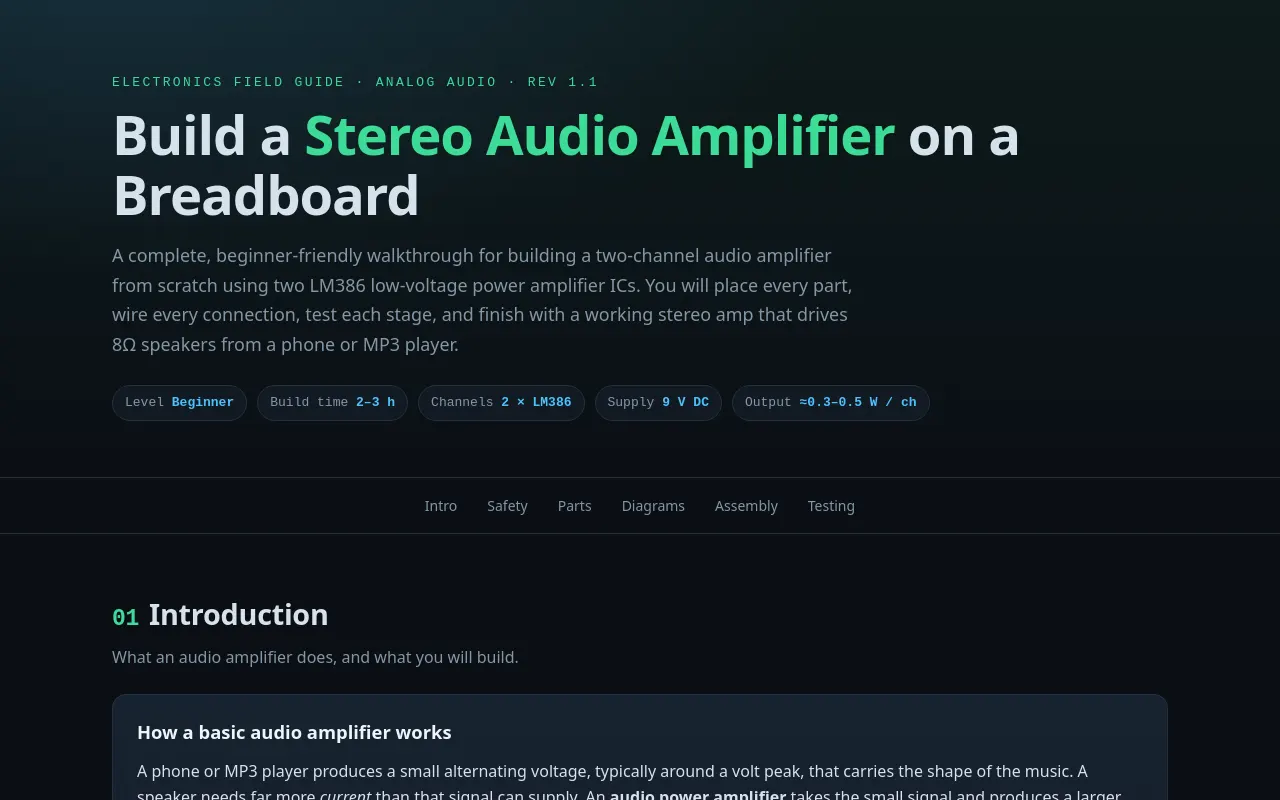
<div class="eyebrow">Electronics Field Guide · Analog Audio · Rev 1.1</div>
<h1>Build a <span>Stereo Audio Amplifier</span> on a Breadboard</h1>
<p class="lead">A complete, beginner-friendly walkthrough for building a two-channel audio amplifier from scratch using two LM386 low-voltage power amplifier ICs. You will place every part, wire every connection, test each stage, and finish with a working stereo amp that drives 8Ω speakers from a phone or MP3 player.</p>
<div class="meta-chips">
<span class="chip">Level <b>Beginner</b></span>
<span class="chip">Build time <b>2–3 h</b></span>
<span class="chip">Channels <b>2 × LM386</b></span>
<span class="chip">Supply <b>9 V DC</b></span>
<span class="chip">Output <b>≈0.3–0.5 W / ch</b></span>
</div>
</div>
</header>
<nav class="toc" aria-label="Guide sections">
<ul>
<li><a href="#intro">Intro</a></li>
<li><a href="#safety">Safety</a></li>
<li><a href="#parts">Parts</a></li>
<li><a href="#diagrams">Diagrams</a></li>
<li><a href="#assembly">Assembly</a></li>
<li><a href="#testing">Testing</a></li>
</ul>
</nav>
<main class="wrap">
<!-- ============ 1. INTRODUCTION ============ -->
<section id="intro" aria-labelledby="h-intro">
<h2 id="h-intro"><span class="num">01</span>Introduction</h2>
<p class="sub">What an audio amplifier does, and what you will build.</p>
<div class="card">
<h3>How a basic audio amplifier works</h3>
<p>A phone or MP3 player produces a small alternating voltage, typically around a volt peak, that carries the shape of the music. A speaker needs far more <em>current</em> than that signal can supply. An <strong>audio power amplifier</strong> takes the small signal and produces a larger copy of the same waveform that has enough current to push a speaker cone back and forth.</p>
<p>The <strong>LM386</strong> is a classic 8-pin audio power amplifier designed for low-voltage battery projects. Internally it has a high-gain input stage and a push-pull output stage. With its gain pins (1 and 8) left open it provides a voltage gain of about <strong>20×</strong>. Adding one 10µF capacitor between pins 1 and 8 raises the gain to about <strong>200×</strong>, which is what you want for a phone-level source.</p>
<p>One LM386 is one <em>mono</em> amplifier. To make a <em>stereo</em> amplifier you build two identical channels that share one 9 V supply and one dual-gang volume potentiometer, giving a left and a right output.</p>
</div>
<h3>Signal flow for one channel</h3>
<figure class="diagram" aria-label="Signal flow block diagram">
<svg viewBox="0 0 900 170" role="img" aria-labelledby="flow-t">
<title id="flow-t">Signal flow: input jack, volume pot, input coupling capacitor, LM386, output capacitor, speaker</title>
<defs>
<marker id="arr" markerWidth="8" markerHeight="8" refX="7" refY="4" orient="auto"><path d="M0 0 L8 4 L0 8 z" fill="#4cc3ff"/></marker>
</defs>
<g fill="#0e1822" stroke="#3d5366" stroke-width="1.5">
<rect x="10" y="55" width="110" height="60" rx="10"/>
<rect x="160" y="55" width="110" height="60" rx="10"/>
<rect x="310" y="55" width="110" height="60" rx="10"/>
<rect x="460" y="30" width="140" height="110" rx="10" stroke="#3ddc97" stroke-width="2.5"/>
<rect x="640" y="55" width="110" height="60" rx="10"/>
<rect x="790" y="55" width="100" height="60" rx="10"/>
</g>
<g font-family="monospace" font-size="14" fill="#d7e2ec" text-anchor="middle">
<text x="65" y="80">Audio in</text><text x="65" y="100" font-size="11" fill="#8397a8">3.5 mm jack</text>
<text x="215" y="80">C1 10µF</text><text x="215" y="100" font-size="11" fill="#8397a8">input coupling</text>
<text x="365" y="80">10k pot</text><text x="365" y="100" font-size="11" fill="#8397a8">volume</text>
<text x="530" y="75" fill="#3ddc97" font-size="20" font-weight="700">LM386</text>
<text x="530" y="98" font-size="12" fill="#8397a8">× 20 (or × 200)</text>
<text x="530" y="118" font-size="11" fill="#8397a8">audio power amp</text>
<text x="695" y="80">C4 220µF</text><text x="695" y="100" font-size="11" fill="#8397a8">output coupling</text>
<text x="840" y="82">8 Ω</text><text x="840" y="100" font-size="11" fill="#8397a8">speaker</text>
</g>
<g stroke="#4cc3ff" stroke-width="2" fill="none" marker-end="url(#arr)">
<line x1="122" y1="85" x2="158" y2="85"/>
<line x1="272" y1="85" x2="308" y2="85"/>
<line x1="422" y1="85" x2="458" y2="85"/>
<line x1="602" y1="85" x2="638" y2="85"/>
<line x1="752" y1="85" x2="788" y2="85"/>
</g>
<text x="450" y="160" text-anchor="middle" font-family="monospace" font-size="13" fill="#8397a8">Each channel is identical. Stereo = two channels sharing one 9 V supply.</text>
</svg>
<figcaption><b>Figure 0.</b> Signal path for one channel. Left to right, the signal grows from millivolts to a full speaker drive.</figcaption>
</figure>
</section>
<!-- ============ 2. SAFETY ============ -->
<section id="safety" aria-labelledby="h-safety">
<h2 id="h-safety"><span class="num">02</span>Safety & Prerequisites</h2>
<p class="sub">Read this before you power anything on.</p>
<div class="callout danger">
<strong>Electrical safety</strong>
This project runs on 9 V DC from a battery or regulated adapter. That is low voltage, but a short across a battery can get very hot, and electrolytic capacitors can vent or burst if installed backwards. Follow every rule below.
</div>
<div class="grid-2">
<div class="card">
<h3>Workbench safety</h3>
<ul class="clean">
<li>Work on a clean, non-conductive surface with good lighting.</li>
<li><strong>Disconnect power</strong> before moving any wire or component.</li>
<li>Never connect the battery or supply directly across the speaker or across a short.</li>
<li>Keep coins, paper clips and loose pins away from the battery clip.</li>
<li>The LM386 gets warm at high volume. Do not grip it for long periods during testing.</li>
<li>Wear eye protection when trimming component leads.</li>
<li>Keep drinks away from the workspace.</li>
</ul>
</div>
<div class="card">
<h3>Hearing safety</h3>
<ul class="clean">
<li>Start with the volume pot at <strong>minimum</strong> before every power-up.</li>
<li>Raise the volume slowly while listening.</li>
<li>A DC offset or wiring fault can produce a loud pop. Keep the speaker away from your ear during first power-up.</li>
<li>Long exposure above 85 dB is harmful. Keep sessions moderate.</li>
</ul>
</div>
</div>
<h3>Tools needed</h3>
<div class="table-wrap">
<table>
<thead><tr><th>Tool</th><th>Required?</th><th>Use</th></tr></thead>
<tbody>
<tr><td>Digital multimeter (DMM)</td><td><span class="tag req">Required</span></td><td>Check voltages, continuity, and resistor values before power-up.</td></tr>
<tr><td>Wire cutters / strippers</td><td><span class="tag req">Required</span></td><td>Trim component leads and strip about 5 mm of insulation from jumper wires.</td></tr>
<tr><td>Needle-nose pliers</td><td><span class="tag">Recommended</span></td><td>Bend component leads and pull wires out of the breadboard.</td></tr>
<tr><td>Breadboard (830 points)</td><td><span class="tag req">Required</span></td><td>Solderless prototyping base.</td></tr>
<tr><td>Soldering iron</td><td><span class="tag">Optional</span></td><td>Only needed if you solder the 3.5 mm jack to a breakout board or a stripboard.</td></tr>
<tr><td>Audio source</td><td><span class="tag req">Required</span></td><td>Phone, MP3 player, or laptop headphone output with a 3.5 mm cable.</td></tr>
<tr><td>Oscilloscope</td><td><span class="tag">Optional</span></td><td>Lets you see the waveform at each stage.</td></tr>
</tbody>
</table>
</div>
<h3>Basic component knowledge</h3>
<div class="grid-2">
<div class="card">
<h3>Electrolytic capacitors</h3>
<p>10µF and 220µF capacitors are <strong>polarized</strong>. The stripe on the side of the can, or the shorter leg, marks the <code>−</code> terminal. Reversing them can cause leakage or rupture. Capacitors <em>block DC</em> and <em>pass AC</em>, which is why they are used to couple signals between stages.</p>
</div>
<div class="card">
<h3>Ceramic capacitors</h3>
<p>0.1µF (100 nF, marked <code>104</code>) ceramic capacitors are not polarized. They are used as high-frequency decoupling right next to the IC supply pin, where they absorb fast current spikes.</p>
</div>
<div class="card">
<h3>Potentiometers</h3>
<p>A 10 kΩ potentiometer has three legs. The two outer legs are the ends of a resistive track, and the middle leg (the <em>wiper</em>) slides along it. Turning it sets how much signal reaches the amplifier. A <em>log (audio, "B")</em> taper sounds more even to the ear than linear.</p>
</div>
<div class="card">
<h3>Integrated circuits</h3>
<p>The LM386 has a notch or dot at one end marking <strong>pin 1</strong>. Looking from above with the notch at the top-left, pins 1–4 run down the left side and pins 5–8 run back up the right side. Pin numbering is counter-clockwise from the notch.</p>
</div>
<div class="card">
<h3>Breadboard basics</h3>
<p>Holes in each numbered column are connected in groups of five: rows <code>a–e</code> form one strip and rows <code>f–j</code> form another. The long rails along the edges run continuously. The centre gap is where a DIP IC straddles the board so its two rows of pins land on separate strips.</p>
</div>
<div class="card">
<h3>Resistor colour code</h3>
<p>10 kΩ = <code>brown · black · orange</code>. 10 Ω = <code>brown · black · black</code>. Always verify with your DMM because colours are easy to misread.</p>
</div>
</div>
<div class="callout warn">
<strong>Polarity check</strong>
Before inserting any electrolytic capacitor, identify its negative side and mark it with a pen if needed. The 3.5 mm jack has three contacts: <strong>tip</strong> (left channel), <strong>ring</strong> (right channel), and <strong>sleeve</strong> (ground). Use a breakout board so you can reach them with jumper wires.
</div>
</section>
<!-- ============ 3. PARTS ============ -->
<section id="parts" aria-labelledby="h-parts">
<h2 id="h-parts"><span class="num">03</span>Complete Parts List</h2>
<p class="sub">Bill of materials for one stereo amplifier: two identical LM386 channels sharing one 9 V supply and one dual-gang volume pot.</p>
<div class="table-wrap">
<table>
<thead>
<tr><th>Component & part number</th><th>Qty</th><th>Purpose / role in the circuit</th></tr>
</thead>
<tbody>
<tr><td>LM386N-1 low-voltage audio power amplifier (DIP-8)<span class="pn">TI LM386N-1 · ON Semi LM386N-1</span></td><td class="qty">2</td><td>Core amplifier, one per channel. Boosts the signal enough to drive an 8 Ω speaker.</td></tr>
<tr><td>Dual-gang 10 kΩ log (audio "B") potentiometer<span class="pn">e.g. Alpha 10K B dual gang</span></td><td class="qty">1</td><td>Master volume. Each gang sets the input level of one channel.</td></tr>
<tr><td>Electrolytic capacitor, 10 µF, 16 V<span class="pn">e.g. Nichicon UKA1C100MDD</span></td><td class="qty">4</td><td>C1 input coupling (x2) blocks DC from the source. C3 gain capacitor (x2) between pins 1 and 8 sets gain to about 200×.</td></tr>
<tr><td>Electrolytic capacitor, 220 µF, 16 V<span class="pn">e.g. Panasonic EEU-FC1C221</span></td><td class="qty">4</td><td>C4 output coupling (x2) blocks DC from the speaker. C2 supply reservoir (x2) on the +9 V rail at pin 6.</td></tr>
<tr><td>Ceramic capacitor, 0.1 µF (100 nF), marked <code>104</code><span class="pn">Multilayer radial, 50 V</span></td><td class="qty">2</td><td>High-frequency supply decoupling, one per channel, placed right at pin 6.</td></tr>
<tr><td>Resistor, 10 kΩ, 1/4 W, 5%<span class="pn">Brown-black-orange</span></td><td class="qty">2</td><td>R2 input bias. Pulls pin 3 to ground so the input has a defined DC level.</td></tr>
<tr><td class="opt">Electrolytic capacitor, 10 µF (optional)<span class="pn">Pin 7 bypass, C5</span></td><td class="qty">2</td><td class="opt">Optional. Pin 7 to ground reduces hiss slightly. Leave pin 7 open if you skip it.</td></tr>
<tr><td class="opt">Resistor 10 Ω + ceramic 0.1 µF (optional Zobel)<span class="pn">Brown-black-black · 104</span></td><td class="qty">2 + 2</td><td class="opt">Optional output damper. Series RC from pin 5 to ground that prevents high-frequency oscillation with long speaker wires.</td></tr>
<tr><td>3.5 mm stereo audio jack breakout (TRS)<span class="pn">e.g. PJ-320A on breakout board</span></td><td class="qty">1</td><td>Audio input. Tip = left, ring = right, sleeve = ground.</td></tr>
<tr><td>8 Ω speaker, 0.5–1 W full-range<span class="pn">e.g. 40 mm 8 Ω 0.5 W</span></td><td class="qty">2</td><td>Output transducers, left and right.</td></tr>
<tr><td>9 V battery with clip, or regulated 9 V DC adapter (500 mA or more)<span class="pn">PP3 or 9 V wall supply</span></td><td class="qty">1</td><td>Power source. The LM386 operates from 4–12 V; 9 V is the sweet spot.</td></tr>
<tr><td>Solderless breadboard, 830 points<span class="pn">With two power rails each side</span></td><td class="qty">1</td><td>Prototyping base.</td></tr>
<tr><td>Jumper wires, solid 22 AWG<span class="pn">Assorted M-M set, about 30 pcs</span></td><td class="qty">~30</td><td>Connect nodes, rails and parts. Use red for +9 V and black for ground.</td></tr>
<tr><td class="opt">SPST toggle switch (optional)<span class="pn">e.g. MTS-102</span></td><td class="qty">1</td><td class="opt">Power switch in series with the + battery lead.</td></tr>
</tbody>
</table>
</div>
<div class="callout">
<strong>Per-channel tally</strong>
Each channel uses: 1 × LM386, 1 × 10 µF (C1), 1 × 10 µF (C3), 1 × 220 µF (C4), 1 × 220 µF (C2), 1 × 0.1 µF ceramic, 1 × 10 kΩ (R2), and 1 speaker. The stereo pot and the 9 V supply are shared. Optional parts are extra.
</div>
</section>
<!-- ============ 4. DIAGRAMS ============ -->
<section id="diagrams" aria-labelledby="h-diagrams">
<h2 id="h-diagrams"><span class="num">04</span>Circuit Diagrams</h2>
<p class="sub">Two views of the same channel. The schematic explains the circuit; the breadboard view shows where each wire goes.</p>
<div class="tabs" role="tablist" aria-label="Diagram view">
<button role="tab" aria-selected="true" aria-controls="tab-schem" id="btn-schem" data-tab="schem">Schematic symbols</button>
<button role="tab" aria-selected="false" aria-controls="tab-bb" id="btn-bb" data-tab="bb">Breadboard wiring</button>
</div>
<div id="tab-schem" class="tabpanel" role="tabpanel" aria-labelledby="btn-schem">
<figure class="diagram">
<svg viewBox="0 0 900 430" role="img" aria-labelledby="schem-t schem-d">
<title id="schem-t">LM386 single-channel schematic</title>
<desc id="schem-d">Audio input jack feeds the top of a 10k volume pot. The wiper goes through a 10 microfarad input capacitor into LM386 pin 3, which is biased to ground by 10k. Pins 2 and 4 are grounded. A 10 microfarad capacitor connects pins 1 and 8. Pin 6 is fed from +9 V with 220 microfarad and 0.1 microfarad decoupling. Pin 5 drives a 220 microfarad output capacitor into an 8 ohm speaker returning to ground.</desc>
<g fill="none" stroke="#4cc3ff" stroke-width="2" stroke-linecap="round" stroke-linejoin="round">
<!-- jack to pot top -->
<path d="M45 215 V150 H150"/>
<!-- wiper to C1 to pin 3 -->
<path d="M160 230 H232"/>
<path d="M244 230 H300 V260 H360"/>
<!-- R2 bias -->
<path d="M300 260 V290"/>
<path d="M300 330 V400"/>
<!-- pot bottom to ground -->
<path d="M150 310 V400"/>
<!-- C3 gain: pin 1 to pin 8 -->
<path d="M360 180 H340 V130 H415"/>
<path d="M430 130 H520 V180 H540"/>
<!-- supply: pin 6 to +9 V rail -->
<path d="M540 260 H600 V70 H700"/>
<!-- C2 and 0.1 uF decoupling to ground -->
<path d="M650 70 V116"/>
<path d="M650 132 V400"/>
<path d="M700 70 V116"/>
<path d="M700 132 V400"/>
<!-- output: pin 5 to C4 to speaker -->
<path d="M540 300 H610"/>
<path d="M624 300 H760"/>
<path d="M800 300 H840 V400"/>
</g>
<!-- Ground returns for pins 2 and 4 -->
<g fill="none" stroke="#4cc3ff" stroke-width="2">
<path d="M360 220 H330 V240"/>
<path d="M360 300 H330 V320"/>
</g>
<g fill="none" stroke="#d7e2ec" stroke-width="2">
<rect x="20" y="215" width="24" height="30" rx="3"/>
<rect x="140" y="150" width="20" height="160" rx="3" stroke="#8397a8"/>
<path d="M160 230 l10 -6 M160 230 l10 6" stroke="#4cc3ff"/>
<path d="M232 214 V246 M244 214 V246"/>
<rect x="292" y="290" width="16" height="40" rx="2"/>
<path d="M420 120 V140 M430 120 V140"/>
<path d="M640 116 H660 M640 132 H660"/>
<path d="M690 116 H710 M690 132 H710"/>
<path d="M616 292 V308 M628 292 V308"/>
<circle cx="780" cy="300" r="20"/>
</g>
<!-- Ground symbols -->
<g fill="none" stroke="#8397a8" stroke-width="2">
<path d="M330 240 V248 M322 248 H338 M325 252 H335 M328 256 H332"/>
<path d="M330 320 V328 M322 328 H338 M325 332 H335 M328 336 H332"/>
<path d="M150 400 H840"/>
<path d="M600 400 H700"/>
</g>
<!-- IC -->
<rect x="380" y="160" width="140" height="160" rx="6" fill="#0e1822" stroke="#3ddc97" stroke-width="2.5"/>
<path d="M442 160 A8 8 0 0 0 458 160" fill="#0b0f14" stroke="#3ddc97" stroke-width="2"/>
<g stroke="#3ddc97" stroke-width="2" fill="none"><path d="M360 180H380M360 220H380M360 260H380M360 300H380M520 180H540M520 220H540M520 260H540M520 300H540"/></g>
<text x="450" y="236" text-anchor="middle" fill="#3ddc97" font-family="monospace" font-size="20" font-weight="700">LM386</text>
<text x="450" y="256" text-anchor="middle" fill="#8397a8" font-family="monospace" font-size="11">audio power amp</text>
<g fill="#d7e2ec" font-family="monospace" font-size="12">
<text x="388" y="184">1</text><text x="388" y="224">2</text><text x="388" y="264">3</text><text x="388" y="304">4</text>
<text x="512" y="184" text-anchor="end">8</text><text x="512" y="224" text-anchor="end">7</text><text x="512" y="264" text-anchor="end">6</text><text x="512" y="304" text-anchor="end">5</text>
</g>
<!-- Labels -->
<g font-family="monospace" font-size="12">
<text x="32" y="206" fill="#4cc3ff" text-anchor="middle">J1</text>
<text x="20" y="262" fill="#8397a8" font-size="11">3.5 mm IN</text>
<text x="184" y="250" fill="#8397a8">wiper</text>
<text x="165" y="300" fill="#d7e2ec">R1 10k</text>
<text x="238" y="206" text-anchor="middle">C1 10µF</text>
<text x="318" y="318" fill="#d7e2ec">R2 10k</text>
<text x="425" y="112" text-anchor="middle">C3 10µF gain</text>
<text x="560" y="224" fill="#8397a8" font-size="10">pin 7 open</text>
<text x="612" y="112" text-anchor="end" font-size="11">C2 220µF</text>
<text x="722" y="124" font-size="11" fill="#8397a8">0.1µF</text>
<text x="610" y="62" fill="#ff5c6c">+9 V</text>
<text x="620" y="286" text-anchor="middle" font-size="11">C4</text>
<text x="620" y="322" text-anchor="middle" font-size="11" fill="#8397a8">220µF</text>
<text x="780" y="340" text-anchor="middle" fill="#3ddc97">8 Ω</text>
<text x="850" y="404" fill="#8397a8" font-size="11">GND</text>
</g>
<g fill="#3ddc97"><circle cx="300" cy="260" r="3.5"/><circle cx="650" cy="70" r="3.5"/><circle cx="700" cy="70" r="3.5"/></g>
</svg>
<figcaption><b>Figure 1. One channel, schematic symbols.</b> Cyan lines carry the audio from jack to speaker. Grey ground symbols tie to the common 0 V bus. Pin numbers match the IC, counter-clockwise from the notch. The 10 µF across pins 1 and 8 raises gain to about 200×; without it, gain is about 20×.</figcaption>
</figure>
</div>
<div id="tab-bb" class="tabpanel" role="tabpanel" aria-labelledby="btn-bb" hidden>
<figure class="diagram">
<svg viewBox="0 0 900 420" role="img" aria-labelledby="bb-t bb-d">
<title id="bb-t">Breadboard wiring guide for one channel</title>
<desc id="bb-d">Top rail is +9 V, bottom rail is ground. The LM386 straddles the centre gap. Wires connect rails to pins 6 and 4, pins 2 and 4 to ground, and the rest as shown.</desc>
<!-- board -->
<rect x="20" y="20" width="860" height="380" rx="14" fill="#0e1822" stroke="#2a3d50" stroke-width="2"/>
<!-- rails -->
<g fill="#1d2b38">
<rect x="50" y="40" width="800" height="22" rx="4"/>
<rect x="50" y="358" width="800" height="22" rx="4"/>
</g>
<text x="40" y="56" text-anchor="end" font-family="monospace" font-size="12" fill="#ff5c6c">+9V</text>
<text x="40" y="374" text-anchor="end" font-family="monospace" font-size="12" fill="#8397a8">GND</text>
<!-- holes grid -->
<g fill="#2e4357" id="holes"></g>
<!-- centre gap -->
<rect x="50" y="190" width="800" height="30" fill="#0b141d"/>
<!-- IC -->
<rect x="350" y="122" width="200" height="132" rx="8" fill="#16242f" stroke="#3ddc97" stroke-width="2"/>
<path d="M430 122 A10 10 0 0 0 450 122" fill="#0e1822" stroke="#3ddc97" stroke-width="2"/>
<text x="450" y="182" text-anchor="middle" font-family="monospace" font-size="18" font-weight="700" fill="#3ddc97">LM386</text>
<g font-family="monospace" font-size="12" fill="#d7e2ec">
<text x="338" y="150" text-anchor="end">1</text><text x="338" y="186" text-anchor="end">2</text>
<text x="338" y="222" text-anchor="end">3</text><text x="338" y="240" text-anchor="end" fill="#8397a8"></text>
<text x="562" y="150">8</text><text x="562" y="186">7</text><text x="562" y="222">6</text><text x="562" y="240"></text>
</g>
<!-- pin numbering row labels: left pins 1-4 top->bottom; right 8-5 top->bottom -->
<g font-family="monospace" font-size="12" fill="#d7e2ec">
<text x="338" y="240" text-anchor="end">4</text>
<text x="562" y="240">5</text>
</g>
<!-- wires (cyan = signal, red = +9 V, grey = ground) -->
<g fill="none" stroke-width="3" stroke-linecap="round">
<path d="M350 150 H320 V230" stroke="#4cc3ff"/>
<path d="M350 186 H330 V340" stroke="#8397a8"/>
<path d="M350 222 H300 V290" stroke="#4cc3ff"/>
<path d="M350 240 H330 V340" stroke="#8397a8"/>
<path d="M550 222 H600 V62" stroke="#ff5c6c"/>
<path d="M550 240 H580 V340" stroke="#f2b233"/>
<path d="M550 150 H580 V130 H470 V130" stroke="#ffb347"/>
<path d="M550 186 H620 V340" stroke="#8397a8"/>
</g>
<!-- parts -->
<g fill="none" stroke="#d7e2ec" stroke-width="2">
<rect x="140" y="230" width="18" height="34" rx="3" stroke="#8397a8"/>
<rect x="250" y="270" width="16" height="48" rx="2"/>
<rect x="650" y="270" width="16" height="48" rx="2" stroke="#ffb347"/>
<rect x="700" y="110" width="30" height="16" rx="3" stroke="#ffb347"/>
</g>
<text x="450" y="410" text-anchor="middle" font-family="monospace" font-size="12" fill="#8397a8">Breadboard view: wire colours follow the schematic. Pin 7 is left unconnected.</text>
</svg>
<figcaption><b>Figure 2. Breadboard wiring guide.</b> Full detail, with each pin's exact row, is given in the assembly steps below. The LM386 straddles the centre gap so pins 1–4 and 5–8 sit on opposite sides.</figcaption>
</figure>
</div>
</section>
<!-- ============ 5. ASSEMBLY ============ -->
<section id="assembly" aria-labelledby="h-assembly">
<h2 id="h-assembly"><span class="num">05</span>Step-by-Step Assembly</h2>
<p class="sub">Build the left channel first, test it, then copy the layout for the right channel. Power off while placing parts.</p>
<ol class="steps">
<li>
<h3>Place the LM386 across the centre gap</h3>
<p>Straddle the LM386 across the centre gap with the notch pointing left. Pins 1–4 go in row <code>e</code> in columns 10, 11, 12 and 13 (pin 1 at column 10, nearest the notch). Pins 5–8 go in row <code>f</code>, on the opposite side of the gap, in columns 13, 12, 11 and 10. Press it down evenly so no pin is bent.</p>
<ul>
<li>Pin 1 → column 10, row e. Pin 2 → column 11, row e. Pin 3 → column 12, row e. Pin 4 → column 13, row e.</li>
<li>Pin 8 → column 10, row f. Pin 7 → column 11, row f. Pin 6 → column 12, row f. Pin 5 → column 13, row f.</li>
</ul>
</li>
<li>
<h3>Build the power rails</h3>
<p>Connect the battery clip (or DC jack) to the rails. Red lead to the top rail labelled +, black lead to the bottom rail labelled −. Bridge the rails with a jumper if your board has split rails. Measure the rails with your DMM before connecting anything else.</p>
<ul>
<li>Expected: about 8.5–9.2 V between the rails with the battery connected.</li>
</ul>
</li>
<li>
<h3>Connect ground pins</h3>
<p>LM386 pins 2 and 4 go to ground. Run a black jumper from pin 4 (column 13, row e) to the bottom rail, and another from pin 2 (column 11, row e) to the bottom rail. Keep both short.</p>
</li>
<li>
<h3>Connect the supply and decoupling</h3>
<p>Pin 6 (column 16, row g) is the supply. Run a red jumper from pin 6 to the top rail. Place the 220µF electrolytic (C2) across the rails, with its <strong>negative leg to the bottom (ground) rail</strong>. Place the 0.1µF ceramic in parallel with it, as close to pin 6 as possible.</p>
<div class="callout warn"><strong>Polarity</strong>Reversing the 220µF is the most common way to pop a capacitor. Check the stripe before you press it in.</div>
</li>
<li>
<h3>Add the gain capacitor</h3>
<p>Place a 10µF electrolytic between pin 1 (column 10, row e) and pin 8 (column 16, row j). Negative leg goes to pin 8 side. This raises gain from about 20× to about 200×. Skip it if you want a quieter but lower-gain amplifier for a loud source.</p>
</li>
<li>
<h3>Build the volume control</h3>
<p>Insert the 10k potentiometer (or one gang of the dual pot) across three rows. Outer legs go to the ground rail and the +9 V rail is <strong>not</strong> connected here: the pot only sees the audio signal, so its ends go to ground and to the input. Connect the wiper (middle leg) to the input coupling capacitor C1.</p>
<ul>
<li>One outer leg to the bottom ground rail.</li>
<li>Other outer leg to the audio input jack's tip (left channel).</li>
<li>Wiper to C1 positive leg.</li>
</ul>
</li>
<li>
<h3>Add input coupling C1 and bias R2</h3>
<p>Place a 10µF electrolytic from the wiper to pin 3 (column 16, row a region on the right half). Its positive leg faces the wiper. Connect the 10k resistor R2 from pin 3 to the bottom ground rail. R2 keeps the input at a defined voltage so the pot does not float.</p>
</li>
<li>
<h3>Wire the output coupling</h3>
<p>Connect pin 5 (column 16, row f) to a 220µF electrolytic (C4). Its positive leg goes to pin 5. Connect C4's negative leg to one lead of the 8 Ω speaker. The other speaker lead goes to the bottom ground rail. The capacitor keeps DC current out of the speaker coil.</p>
</li>
<li>
<h3>Optional pin 7 bypass and Zobel damper</h3>
<p>Pin 7 can be left open (the default) or bypassed with a 10µF to ground to slightly reduce hiss. For long speaker wires, add a 10Ω resistor in series with a 0.1µF ceramic from pin 5 to ground, placed close to the IC.</p>
</li>
<li>
<h3>Wire the stereo input jack</h3>
<p>Connect the 3.5 mm breakout to the breadboard: <strong>tip</strong> goes to the left volume pot, <strong>ring</strong> goes to the right volume pot, and <strong>sleeve</strong> goes to ground. Use one shared pot-to-jack ground for both channels.</p>
</li>
<li>
<h3>Build the right channel</h3>
<p>Repeat steps 1–9 for the second LM386, using the second gang of the stereo pot and the right speaker. Keep the two channels physically separated on the breadboard and use short leads to reduce crosstalk and hum.</p>
</li>
<li>
<h3>Connect the power switch and battery</h3>
<p>If using a switch, place it in series with the red battery lead. Connect the battery only after you have finished both channels and checked every connection against the schematic.</p>
</li>
</ol>
</section>
<!-- ============ 6. TESTING ============ -->
<section id="testing" aria-labelledby="h-testing">
<h2 id="h-testing"><span class="num">06</span>Testing & Troubleshooting</h2>
<p class="sub">Verify before you power up, then fault-find methodically.</p>
<h3>Pre-power checklist</h3>
<ul class="check">
<li>Every LM386 pin sits in its own row, with no pins bent under the package.</li>
<li>Both 220µF capacitors and both 10µF capacitors are installed with negative legs on the ground side.</li>
<li>Red leads only touch the + rail, black leads only touch the − rail.</li>
<li>DMM continuity shows no short between +9 V and GND with the battery disconnected.</li>
<li>Volume pots are at minimum (fully counter-clockwise).</li>
<li>Speakers are not shorted and are connected only through the output capacitor.</li>
</ul>
<h3>Safe first power-up</h3>
<ol class="steps">
<li>
<h3>Connect the battery with the speakers disconnected</h3>
<p>Measure +9 V on pin 6 and about 4.5 V on pin 5 (the output rests near half supply). Measure pin 3 at about 0 V to 1 V with no signal.</p>
</li>
<li>
<h3>Check current draw</h3>
<p>With a series DMM set to mA, a silent LM386 draws only a few milliamps. Anything over about 50 mA at idle means a short or a wrong connection. Disconnect power and re-check.</p>
</li>
<li>
<h3>Reconnect speakers and listen quietly</h3>
<p>Plug in the audio source, keep the volume at minimum, then raise it slowly. Clean sound with no hum means the basics are right.</p>
</li>
</ol>
<h3>Common mistakes and fixes</h3>
<div class="table-wrap">
<table>
<thead><tr><th>Symptom</th><th>Likely cause</th><th>Fix</th></tr></thead>
<tbody>
<tr><td class="sym">No sound at all</td><td>Pin 6 not connected to +9 V, or input jack not wired to the pot.</td><td class="fix">Check DMM voltage on pin 6. Re-seat the jack and pot wiper.</td></tr>
<tr><td class="sym">Loud hum (50/60 Hz)</td><td>Ground loop, or long unshielded input wires.</td><td class="fix">Join all grounds at one point near the battery. Shorten input leads.</td></tr>
<tr><td class="sym">Distorted, buzzing sound</td><td>Supply too low (weak battery), or 220µF missing.</td><td class="fix">Measure battery voltage under load. Replace it and fit C2.</td></tr>
<tr><td class="sym">Oscillation / high squeal</td><td>Feedback through long speaker wires or missing decoupling.</td><td class="fix">Add the 0.1µF across pin 6, and the optional 10Ω + 0.1µF Zobel on pin 5.</td></tr>
<tr><td class="sym">Warm IC, fast drain</td><td>Output shorted to ground or to +9 V.</td><td class="fix">Power off immediately. Check speaker leads and C4 orientation.</td></tr>
<tr><td class="sym">Loud pop at power-on</td><td>Output capacitor reversed or DC on the speaker.</td><td class="fix">Power off, turn the volume to zero, and check polarity of C4.</td></tr>
<tr><td class="sym">One channel dead</td><td>Wiper or input capacitor not in the correct row.</td><td class="fix">Swap the source to the other side of the jack to confirm, then trace the wiring.</td></tr>
<tr><td class="sym">Capacitor hot or bulging</td><td>Reversed electrolytic polarity.</td><td class="fix">Power off at once, disconnect battery, and replace the part. Never reuse it.</td></tr>
</tbody>
</table>
</div>
<div class="callout danger">
<strong>Feedback loops and stability</strong>
The LM386 is a high-gain amplifier, so any path from the output back to the input can create oscillation. Keep the input wiring away from the speaker wires, use short leads, and keep the decoupling capacitors next to the IC. If you hear a whine that changes with volume, first check these, then add the Zobel network.
</div>
</section>
</main>
<footer>
<div class="wrap">
Stereo LM386 breadboard amplifier · Field guide Rev 1.1 · Always power off before rewiring.
</div>
</footer>
<script>
(function () {
var btns = document.querySelectorAll('.tabs button[data-tab]');
btns.forEach(function (b) {
b.addEventListener('click', function () {
btns.forEach(function (o) { o.setAttribute('aria-selected', 'false'); });
b.setAttribute('aria-selected', 'true');
var target = b.getAttribute('data-tab');
document.querySelectorAll('.tabpanel').forEach(function (p) {
p.hidden = (p.id !== 'tab-' + target);
});
});
});
})();
</script>
</body>
</html>
<!-- agent-meta {"model":"anthropic/claude-haiku-5.5","provider":"openrouter","persona":"full","sessionId":"e8c5448a-e5db-47d3-8ace-f014daf86539","tokensIn":308242,"tokensOut":155284,"tokensTotal":463526,"cost":0.08652481000000002,"turns":12,"toolCalls":15,"failedToolCalls":2,"timestamp":"2026-10-08T01:32:37.556Z"} -->