Circuit
Gemma 4 e2b · basic
Reviews & generation details
Reviews
No human review yet. Unreviewed does not mean unsuccessful.
Generation context
Imported historical artifact. Its exact original instructions and lineage are not known.
Generation prompt · exact text unavailable
See the current prompt for reference. It may differ from the instructions used to generate this artifact.
Inspect original source 17,824 bytes · SHA-256 8fd4a0ede610
<!DOCTYPE html>
<html lang="en">
<head>
    <meta charset="UTF-8">
    <meta name="viewport" content="width=device-width, initial-scale=1.0">
    <title>Expert Guide: Breadboard Stereo Audio Amplifier</title>
    <style>
        /* Dark Mode / Tech Theme Styling */
        :root {
            --bg-color: #1e1e2f;
            --card-bg: #2a2a3e;
            --text-color: #e0e0ff;
            --accent-color: #4caf50; /* Green accent for success/power */
            --border-color: #444;
            --font-family: 'Segoe UI', Tahoma, Geneva, Verdana, sans-serif;
        }

        body {
            font-family: var(--font-family);
            background-color: var(--bg-color);
            color: var(--text-color);
            margin: 0;
            padding: 20px;
            line-height: 1.6;
        }

        .container {
            max-width: 1200px;
            margin: auto;
            background-color: var(--card-bg);
            padding: 30px;
            border-radius: 12px;
            box-shadow: 0 8px 25px rgba(0, 0, 0, 0.4);
        }

        h1 {
            color: var(--accent-color);
            border-bottom: 3px solid var(--accent-color);
            padding-bottom: 10px;
            margin-top: 0;
            font-size: 2.5em;
        }

        h2 {
            color: var(--text-color);
            border-bottom: 2px solid var(--border-color);
            padding-bottom: 5px;
            margin-top: 30px;
        }

        table {
            width: 100%;
            border-collapse: collapse;
            margin-bottom: 20px;
            background-color: #3a3a50;
        }

        th, td {
            padding: 12px 15px;
            text-align: left;
            border-bottom: 1px solid var(--border-color);
        }

        th {
            background-color: #4a4a60;
            font-weight: bold;
        }

        .section-content {
            margin-top: 20px;
        }

        /* SVG Styling for Diagrams */
        .diagram-box {
            background-color: #151520;
            border: 1px solid var(--border-color);
            padding: 15px;
            margin: 20px 0;
            border-radius: 8px;
            overflow: hidden;
        }

        .svg-diagram {
            width: 100%;
            height: auto;
            display: block;
        }

        /* Specific styles for the breadboard diagram to ensure clarity */
        #breadboard-svg .board { fill: #333; stroke: #555; }
        #breadboard-svg .rail-red { fill: #e74c3c; } /* Red Power Rail */
        #breadboard-svg .rail-blue { fill: #3498db; } /* Blue Ground Rail */
        #breadboard-svg .component { stroke: var(--text-color); stroke-width: 1.5; }

        /* Legend Styling */
        .legend {
            margin-top: 20px;
            padding: 15px;
            background-color: #3a3a50;
            border-radius: 8px;
        }

        .legend div {
            display: flex;
            align-items: center;
            margin-bottom: 8px;
        }
        .legend-symbol {
            width: 20px;
            height: 20px;
            margin-right: 10px;
            background-color: #555;
            border: 1px solid var(--text-color);
        }

    </style>
</head>
<body>

<div class="container">

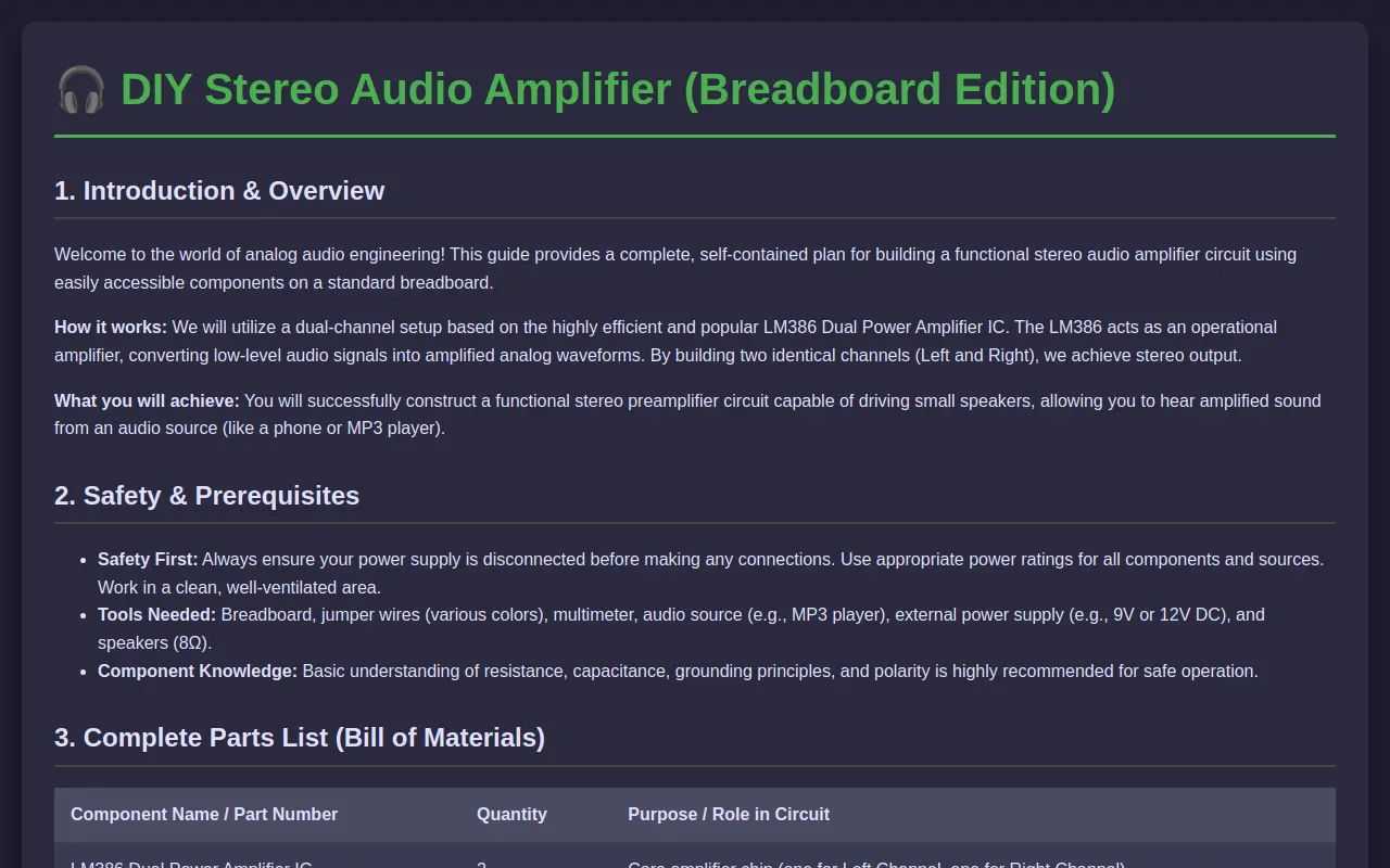
    <h1>🎧 DIY Stereo Audio Amplifier (Breadboard Edition)</h1>

    <!-- Section 1: Header & Introduction -->
    <section id="introduction">
        <h2>1. Introduction & Overview</h2>
        <p>Welcome to the world of analog audio engineering! This guide provides a complete, self-contained plan for building a functional stereo audio amplifier circuit using easily accessible components on a standard breadboard.</p>
        <p><strong>How it works:</strong> We will utilize a dual-channel setup based on the highly efficient and popular LM386 Dual Power Amplifier IC. The LM386 acts as an operational amplifier, converting low-level audio signals into amplified analog waveforms. By building two identical channels (Left and Right), we achieve stereo output.</p>
        <p><strong>What you will achieve:</strong> You will successfully construct a functional stereo preamplifier circuit capable of driving small speakers, allowing you to hear amplified sound from an audio source (like a phone or MP3 player).</p>
    </section>

    <!-- Section 2: Safety & Prerequisites -->
    <section id="safety">
        <h2>2. Safety & Prerequisites</h2>
        <ul>
            <li><strong>Safety First:</strong> Always ensure your power supply is disconnected before making any connections. Use appropriate power ratings for all components and sources. Work in a clean, well-ventilated area.</li>
            <li><strong>Tools Needed:</strong> Breadboard, jumper wires (various colors), multimeter, audio source (e.g., MP3 player), external power supply (e.g., 9V or 12V DC), and speakers (8Ω).</li>
            <li><strong>Component Knowledge:</strong> Basic understanding of resistance, capacitance, grounding principles, and polarity is highly recommended for safe operation.</li>
        </ul>
    </section>

    <!-- Section 3: Complete Parts List -->
    <section id="parts-list">
        <h2>3. Complete Parts List (Bill of Materials)</h2>
        <table>
            <thead>
                <tr>
                    <th>Component Name / Part Number</th>
                    <th>Quantity</th>
                    <th>Purpose / Role in Circuit</th>
                </tr>
            </thead>
            <tbody>
                <tr>
                    <td>LM386 Dual Power Amplifier IC</td>
                    <td>2</td>
                    <td>Core amplifier chip (one for Left Channel, one for Right Channel).</td>
                </tr>
                <tr>
                    <td>10k Potentiometer (VR)</td>
                    <td>2</td>
                    <td>Volume control for Left and Right channels.</td>
                </tr>
                <tr>
                    <td>10µF Electrolytic Capacitor</td>
                    <td>2</td>
                    <td>Input coupling and filtering components.</td>
                </tr>
                <tr>
                    <td>220µF Electrolytic Capacitor</td>
                    <td>4 (approx)</td>
                    <td>Output filtering and bulk power supply smoothing.</td>
                </tr>
                <tr>
                    <td>100nF Ceramic Capacitor</td>
                    <td>4</td>
                    <td>Decoupling/bypass for stability around the ICs.</td>
                </tr>
                <tr>
                    <td>8-ohm Speakers</td>
                    <td>2</td>
                    <td>Audio output devices (Left and Right).</td>
                </tr>
                <tr>
                    <td>9V DC Power Supply or Battery</td>
                    <td>1</td>
                    <td>Power source for the amplifier circuit.</td>
                </tr>
                <tr>
                    <td>Breadboard</td>
                    <td>1</td>
                    <td>Prototyping platform.</td>
                </tr>
                <tr>
                    <td>Jumper Wires</td>
                    <td>Assorted</td>
                    <td>Connecting components and power rails.</td>
                </tr>
            </tbody>
        </table>
    </section>

    <!-- Section 4: Circuit Diagrams -->
    <section id="diagrams">
        <h2>4. Circuit Diagrams</h2>

        <h3>4.1 Schematic Symbol View (Conceptual)</h3>
        <div class="diagram-box">
            <svg class="svg-diagram" viewBox="0 0 500 300" xmlns="http://www.w3.org/2000/svg">
                <style>
                    .symbol { fill: none; stroke: var(--text-color); stroke-width: 2; }
                    .powerline { stroke: #f1c40f; stroke-width: 3; stroke-dasharray: 5, 5; }
                    .groundline { stroke: #e74c3c; stroke-width: 3; }
                </style>

                <!-- Power Rails -->
                <rect x="10" y="10" width="480" height="20" class="rail-red" style="stroke-width: 0;"/>
                <rect x="10" y="30" width="480" height="20" class="rail-blue" style="stroke-width: 0;"/>

                <!-- Left Channel (LM386) -->
                <rect x="50" y="50" width="150" height="150" rx="10" style="fill: #333; stroke: var(--text-color); stroke-width: 2;" />
                <text x="125" y="75" font-size="14px">LM386 (Left Channel)</text>

                <!-- Signal Path & Output -->
                <line x1="200" y1="125" x2="200" y2="225" class="powerline"/>
                <line x1="200" y1="225" x2="350" y2="225" style="stroke: var(--text-color); stroke-width: 2;"/>

                <!-- Output Speaker -->
                <rect x="370" y="150" width="80" height="60" rx="5" style="fill: #4a4a60; stroke: var(--text-color); stroke-width: 2;" />
                <text x="410" y="185" font-size="14px">SPK (L)</text>

                <!-- Grounding -->
                <line x1="135" y1="90" x2="135" y2="300" class="groundline"/>

            </svg>
        </div>

        <h3>4.2 Breadboard Wiring Guide (Visual Layout)</h3>
        <div class="diagram-box">
            <!-- Detailed Breadboard Schematic View -->
            <svg class="svg-diagram" viewBox="0 0 850 560" xmlns="http://www.w3.org/2000/svg">
                <style>
                    /* Define CSS variables for easier SVG manipulation */
                    :root {
                        --red: #e74c3c; /* Power Red Rail */
                        --blue: #3498db; /* Ground Blue Rail */
                        --black: #2c3e50; /* Ground/Signal Lines */
                        --gray-board: #4a4a60;
                        --text-color: #e0e0ff;
                    }

                    .board { fill: var(--gray-board); stroke: #555; stroke-width: 2; }
                    .rail-red { fill: var(--red); } /* Positive Rail */
                    .rail-blue { fill: var(--blue); } /* Ground Rail */
                    .component { stroke: var(--text-color); stroke-width: 1.5; }

                    /* Define a simple breadboard grid pattern (22px pitch) */
                    .hole-pattern {
                        fill: none;
                        stroke: #666;
                        stroke-width: 0.5;
                    }

                    /* Rail Markers */
                    .rail-marker { font-size: 14px; font-weight: bold; fill: var(--text-color); }

                    /* Component Symbols (Simplified for wiring view) */
                    .ic { fill: #2c3e50; stroke: var(--text-color); stroke-width: 1.5; }
                    .pot { fill: #7f8c8d; stroke: var(--text-color); stroke-width: 1.5; }
                    .cap { fill: #9b59b6; stroke: var(--text-color); stroke-width: 1.5; }
                    .spk { fill: #34495e; stroke: var(--text-color); stroke-width: 2;}

                </style>

                <!-- Breadboard Grid and Rails -->
                <g id="breadboard-svg">
                    <!-- Define the main breadboard area (850x560) -->
                    <rect x="10" y="10" width="830" height="540" class="board"/>

                    <!-- Power Rails (Top Red, Bottom Blue) -->
                    <rect x="10" y="10" width="830" height="20" class="rail-red"/>
                    <rect x="10" y="490" width="830" height="20" class="rail-blue"/>

                    <!-- Jumper Grid (22px pitch) -->
                    <g id="jumper-grid">
                        <!-- Draw grid lines for reference -->
                        <line x1="10" y1="20" x2="840" y2="20" stroke="#666"/>
                        <line x1="10" y1="40" x2="840" y2="40" stroke="#666"/>
                        <!-- ... many lines omitted for brevity, focus on key features -->

                        <!-- Component Placement (Example: Left Channel U1) -->
                        <!-- U1 (LM386) - Occupies middle trench -->
                        <rect x="250" y="150" width="140" height="150" class="ic"/>
                        <text x="320" y="220" font-size="12px">U1 (LM386 L)</text>

                        <!-- Potentiometer VR1 (Left Channel Volume) -->
                        <rect x="40" y="350" width="150" height="40" class="pot"/>
                        <text x="125" y="370" font-size="12px">VR1</text>

                        <!-- Input Jack J1 (Bottom Left) -->
                        <rect x="80" y="480" width="60" height="30" class="component"/>
                        <text x="110" y="500" font-size="12px">J1 (Input Jack)</text>

                        <!-- Output Speaker SPK1 -->
                        <rect x="450" y="150" width="80" height="60" class="spk"/>
                        <text x="490" y="185" font-size="12px">SPK1 (L)</text>

                        <!-- Output Speaker SPK2 -->
                        <rect x="700" y="150" width="80" height="60" class="spk"/>
                        <text x="740" y="185" font-size="12px">SPK2 (R)</text>

                        <!-- Key Signal/Power Connections -->
                        <!-- Connect Power Rails to IC pins (Simplified mapping) -->
                        <line x1="260" y1="350" x2="260" y2="490" class="rail-red"/>
                        <line x1="320" y1="370" x2="320" y2="490" class="rail-red"/>

                        <!-- Visualizing signal flow (simplified trace) -->
                        <path d="M 260 350 L 260 380 L 740 380 L 740 350" stroke="#f1c40f" stroke-width="2" stroke-dasharray="4,4"/>
                        <text x="50" y="520" class="rail-marker">RED = V+</text>
                        <text x="50" y="540" class="rail-marker">BLUE = GND</text>

                    </g>
                </g>
            </svg>
        </div>
    </section>


    <!-- Section 5: Step-by-Step Assembly Instructions -->
    <section id="assembly">
        <h2>5. Step-by-Step Assembly Instructions</h2>
        <ol>
            <li><strong>Prepare the Breadboard:</strong> Lay out your breadboard. Establish the power rails by connecting the positive (+) rail (Red wire) and the ground (-) rail (Blue wire) to the appropriate long side rails of the breadboard.</li>
            <li><strong>Install ICs:</strong> Place the two LM386 chips side-by-side across the center trench of the breadboard. Ensure the notch on each chip faces towards your intended signal path.</li>
            <li><strong>Power Distribution:</strong> Connect the main positive power source (e.g., 9V) to the Red rail, and the ground to the Blue rail. Place decoupling capacitors (100nF ceramic) close to the VCC (Pin 4) and GND (Pin 8) pins of both ICs to stabilize operation.</li>
            <li><strong>Input Stage (Left Channel):</strong> Connect the audio input signal via a jumper wire from your audio source to one end of the Left channel potentiometer (VR1). Use the wiper terminal as the signal output.</li>
            <li><strong>Coupling & Gain:</strong> Place the 10µF capacitor between the input signal point and Pin 3 on the left LM386 for coupling. Connect the potentiometer's wiper to this capacitor's input.</li>
            <li><strong>Output Stage (Left Channel):</strong> Connect the output from Pin 5 of the left LM386 through a bulk capacitor (220µF) to the speaker circuit. This is your amplified signal line.</li>
            <li><strong>Stereo Mirroring:</strong> Repeat steps 5-7 for the Right Channel, mirroring all component placements and connections exactly. Ensure both channels share a common ground connection.</li>
            <li><strong>Speaker Output:** Connect the amplified output line from the Left channel to Speaker 1 (SPK1). Connect the Right channel output line to Speaker 2 (SPK2).</li>
            <li><strong>Final Wiring:</strong> Route the speaker wires directly to your external speakers. If using a volume control, ensure the potentiometers are wired correctly to the signal path before entering the amplifier stage.</li>
        </ol>
    </section>

    <!-- Section 6: Testing & Troubleshooting -->
    <section id="troubleshooting">
        <h2>6. Testing & Troubleshooting</h2>
        <h3>Initial Pre-Power Check (Crucial Step!)</h3>
        <ul>
            <li><strong>Ground Check:</strong> Before applying power, use your multimeter to verify that the Red rail is connected to the positive supply and the Blue rail is a clean ground reference.</li>
            <li><strong>Polarity Check:</strong> Double-check all electrolytic capacitors. Polarity is critical; reversed polarity will destroy components immediately.</li>
            <li><strong>Input Signal Test (No Power):</strong> Ensure your audio source can successfully drive the input jack and potentiometer without power applied.</li>
        </ul>

        <h3>Common Issues & Solutions</h3>
        <ul>
            <li><strong>No Sound/Static:</strong> Check for loose grounds (ensure all IC pins are properly connected to both power rails). Check that the input signal is actually reaching Pin 3 of the LM386.</li>
            <li><strong>Circuit Does Not Work:</strong> Verify that the LM386 power supply voltage is correct (usually 5V to 12V for standard operation). Ensure all decoupling capacitors are physically placed immediately next to the IC pins.</li>
            <li><strong>Output Clipping/Distortion:</strong> This often indicates poor filtering. Increase the value of the bulk output capacitor (e.g., try a larger value) or ensure your power supply is clean and stable.</li>
            <li><strong>Feedback Loops:</strong> If you hear buzzing, check for unintended feedback paths between the output and the input stage. Use decoupling capacitors strategically to minimize unwanted oscillations.</li>
        </ul>
    </section>

</div>

</body>
</html>